Zamp Solar
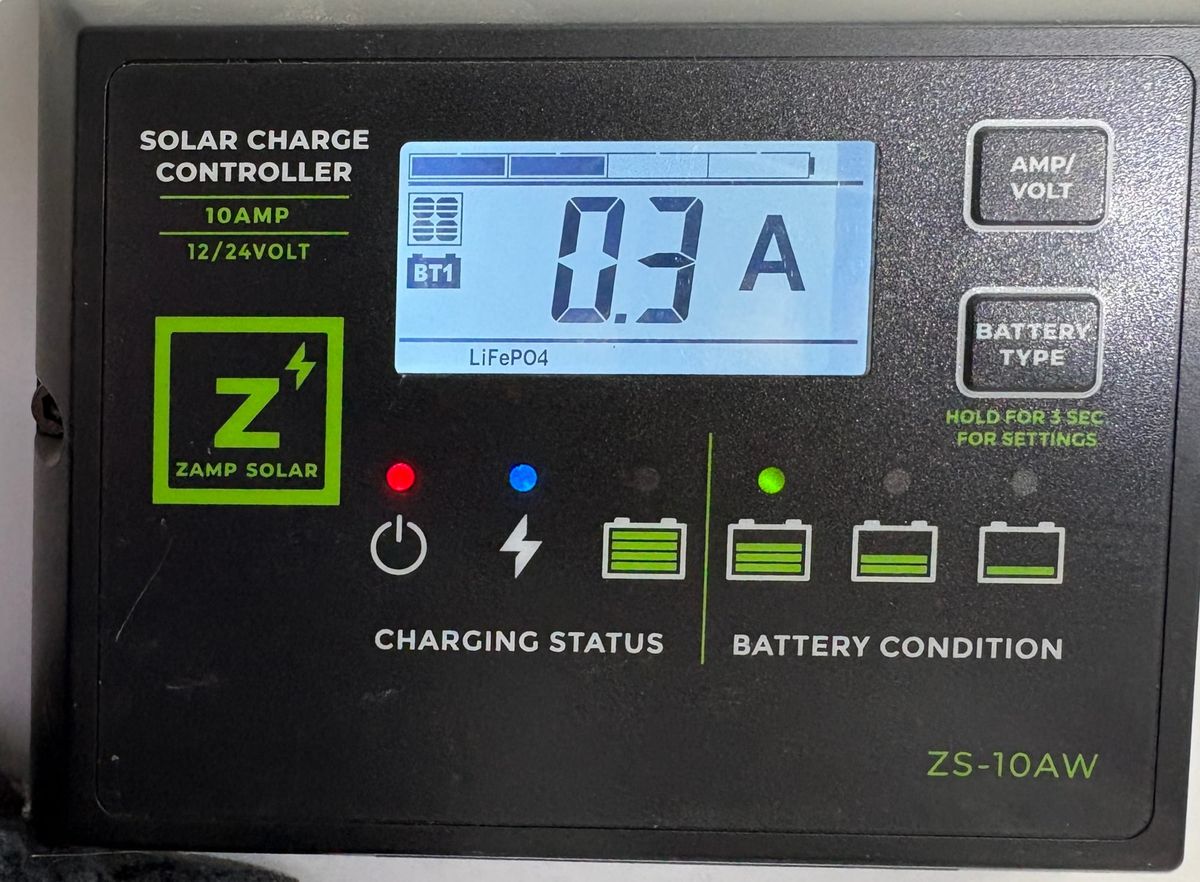
There is a feature of the Escapod Topo 2 that is shortchanging you in terms of solar capacity. Ever since I got my Escapod I would look at the solar charge controller and see it display 13.3 volts and maybe up to 5 Amps at best on a sunny day. I fiddled with the angle of the solar panel but got nothing better. The solar panel is rated at 140W and while it is often difficult to get the full rated power, 13v x 5A is only 65 watts. (At my latitude in the summer the most I could expect out of the panel is about 130W.)
I bought my Escapod used and the panel was dinged. Also at the time there was too not much to power. Lights, fans (ceiling and heat), water pump and it was fine. No AC and no inverter. The panel kept up with everything fine.
Then I bought an ARB Fridge and installed it. Suddenly if I was not in strong sunlight most of the day the battery was steadily declining. I have a separate solar panel and battery in my truck which I use to top-up the Escapod every few days. In Canada at a shady campground recently I got down to 10% even with a top-up charge from my truck.
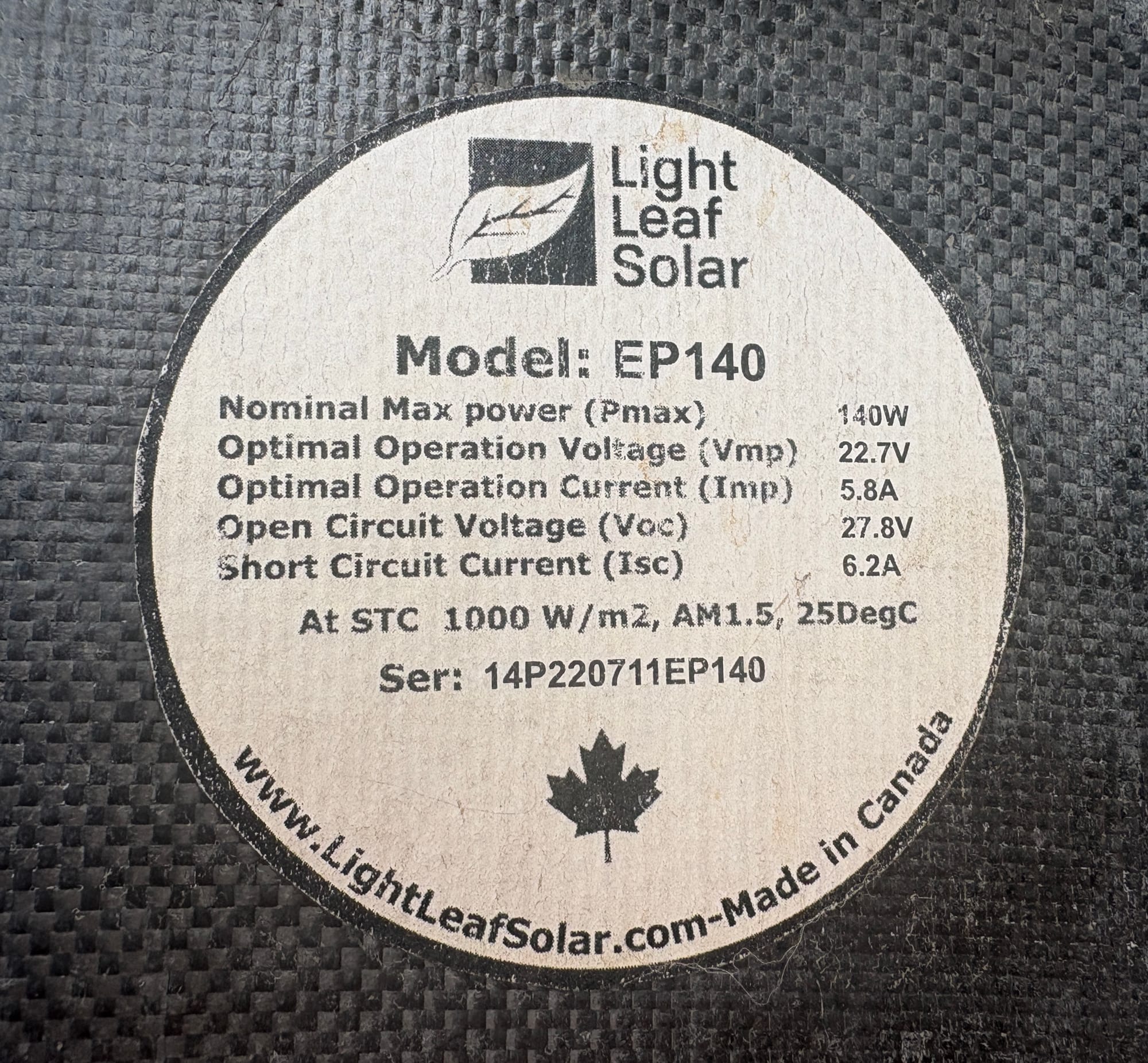
This brought me back to why I didn’t get close to the nameplate power on the panel. As you can see from above under optimal conditions it should deliver 22.7V and 5.8A or 22.7 x 5.8 = 131.66 watts which is less than than the nameplate but this is common, but still more than the 65 watts I have been seeing.
The Zamp ZS-10A on my Topo 2 is the solar charge controller. Its job is to take the higher solar voltage around 23 volts and take it down to the 13 or so volts to charge the battery. Solar charge controllers come in two types PWM and MPPT. PWM is simpler and cheaper and this is the type the Zamp uses. The difficulty is that the PWM controllers simply ‘trims off’ (regulates) the excess voltage down to the charging voltage by ‘throwing away’ the excess voltage. Thus the LightLeaf 22.7v at 5.8A becomes perhaps 13v at 5.8A or 75.4W. It will never reach the full spec of the panel. The efficiency becomes 75.4W/131.66W= 57%, not very good but typical of PWM charge controllers under these conditions.
An MPPT charge controller is much more sophisticated and therefore efficient. It tracks the voltage and current from the panel as it changes under different lighting conditions and then converts that voltage and current directly to the battery voltage and current. When the voltage is higher than needed it takes the excess voltage and converts it to additional current at the lower battery voltage. This should allow operation much closer to the full specs of the panel.
I purchased a Victron MPPT charge controller to replace the Zamp. It claims efficiency as high as 99% so one can see how an improvement could be made. There are probably other cheaper MPPT charge controllers. I bought the Victron 100/30 which is complete overkill as it handles 100v of panel voltage and 30A of charge current and a total of 440w of total solar power. I did this as I plan to add more panels in the future. This unit is $135. (The 75/15 model is adequate for the LightLeaf panel at 200W capacity and is only $70 for instance.)
(I am not making any special endorsement about Victron. I like their products and have used them elsewhere so they are what I know. There are many options from many vendors and you can probably find one cheaper if on a tighter budget. Just make sure you avoid PWM or you will have spent your money for nothing.)
When choosing an MPPT you need to match your panel specs for voltage and current as well as the overall panel wattage rating. The MPPT should be rated to accept the open circuit (OC) voltage and short circuit current from your selected panel. For the Lightleaf it is 27.8v and 6.2A respectively. (Interestingly the Zamp does not accept an OC voltage this high! So it is technically mismatched. Obviously they seem to not suffer damage or perhaps the panel rarely gets to the OC voltage.)
The smaller Victron 75/15 model handles 75 volts input and 15 amps of current so readily handles the LighLeaf specs. The 75/15 is rated at 200 watts of panel power which is also higher than LightLeaf’s 140W max power spec. The 200 watt limit for the MPPT means there is little headroom for more solar panels.
Victron does not have a display built-in like the Zamp unit does. It relies on an app and Bluetooth to show charging status. The Simarine will still work as normal and you will have a hole in the cabinet wall if you remove the Zamp or you can just leave it there disconnected as you see fit. Victron, for about another $50 plus cable, will sell you a small display you could mount in the cabin if you want that extra visual reassurance. I use the app.
Also an MPPT needs to see some voltage more than the battery voltage to function. For Victron this is 5 volts. So if the charge is happening at say 13 volts then the panel needs to produce at least 18 volts in this example. (Once charging has started the Victron will continue charging down to a 1 volt difference.) This is not a practical limitation of the LightLeaf panel.
Installation
Before fiddling with the Zamp I recommend disconnecting the solar panel at the back of the kitchen hatch. Also disconnect one battery terminal and also make sure shore power is disconnected. The lithium battery can deliver a tremendous amount of current and the fuse to the battery is 250 amps! which is crazy high. 12 volts will not electrocute you but 250 amps will melt metal (think metal wrenches) and cause burns and blindness. I wore eye protection the entire time.
The battery is accessed from the kitchen by removing the center set of shelves. There are no screws so everything just slides out. Behind that is a panel with two finger holes top and bottom held in place with magnets. Put your fingers through the holes and work the panel free. You should see the following.
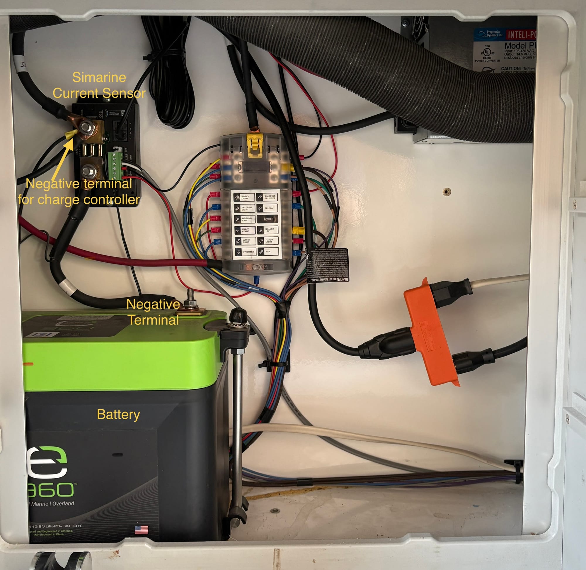
I removed the negative terminal as it was the simplest to reach. Cover the end of the cable with electrical tape to keep it from making accidental contact.
I began the installation by removing the Zamp controller. It is a simple matter of a hex wrench to unscrew the Zamp from the bulkhead it is mounted to. Below is what the back of the unit looks like.
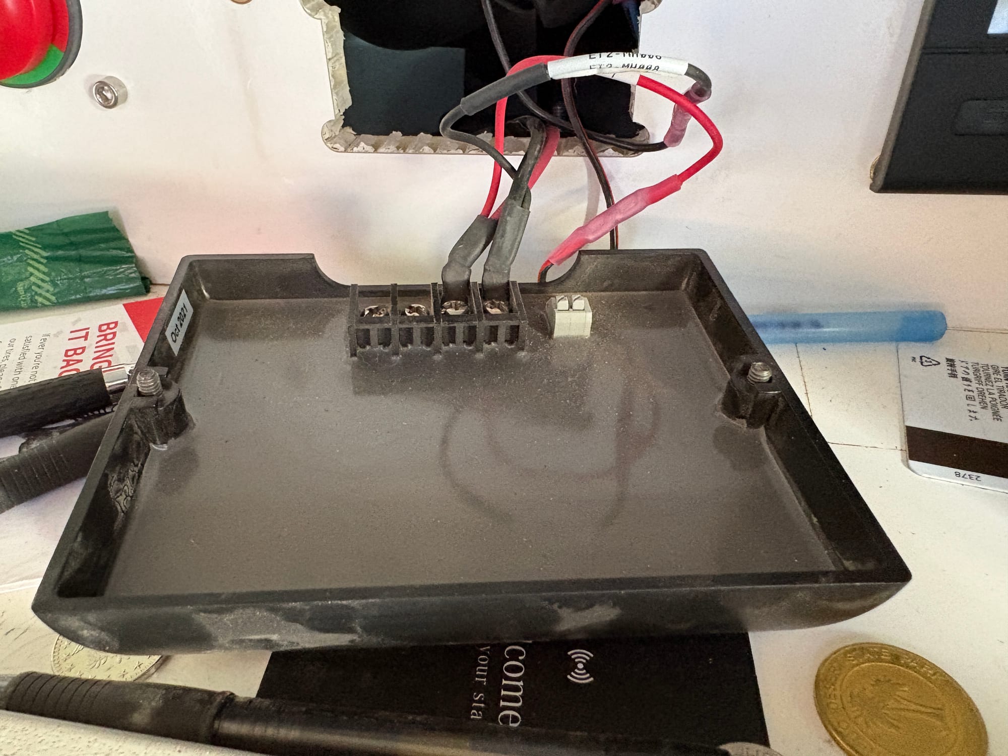
In the photo above the two terminals on the left are where the solar (PV) wires are connected (here they have been removed already). On mine the negative wire is white and the positive is black. I used a multimeter to confirm this. You should do the same. (This will require the solar panel to be reconnected and with some light shining on it. Disconnect the panel after confirming.) The right two wires are connected to the battery for the charging function.
I left the two battery wires for three reasons. They are also the power supply for the Truma display on the right. It was simpler to just leave them there. The next reason is I didn’t want to figure out how to cover the hole. Third I decided that if something goes wrong with my new charge controller I can reconnect the Zamp as a redundant unit. The Zamp is also useful in this configuration where it functions as a battery volt meter. If you press either button the green LED with give another view on the state of charge. Make sure the unit is still configured to LiFePO4.
Next I pulled the PV cable from the back of the kitchen. This requires the cutting board to be removed as well as the panel holding the kitchen knives. This second panel is fiddly to get out and I really have no technique I can help you with.
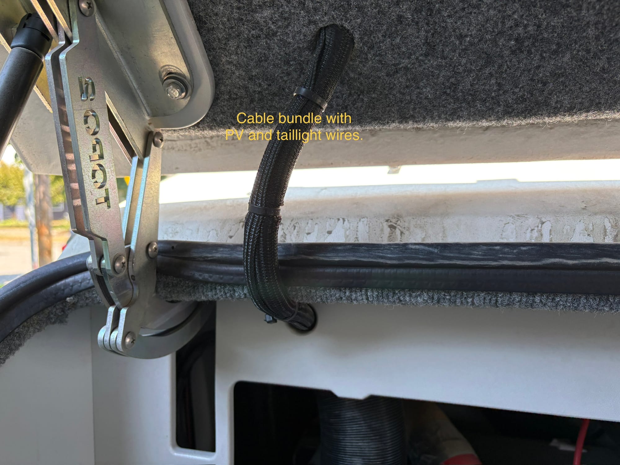
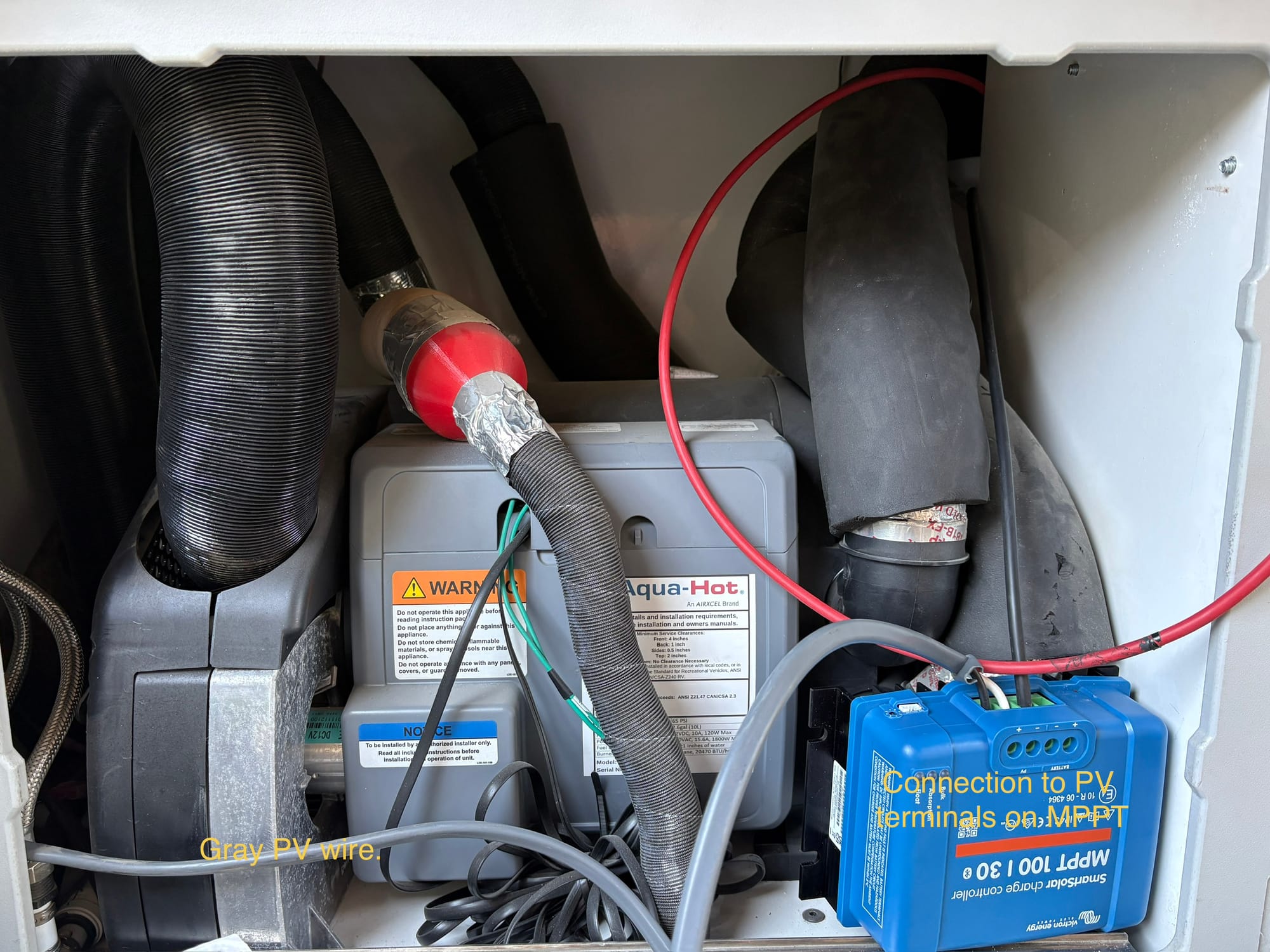
The PV wires in the bundle emerge behind the panel. Mine were bundled in a gray sheath. I pulled the now free end toward me until I had the terminals I had disconnected earlier in my hand. I then cut these off as the the new MPPT uses terminals that take bare stripped wires. I stripped about 1/2 inch from the ends of these wires and connected them to the MPPT.
DO NOT CONNECT THE SOLAR PANEL TO THE MPPT CHARGE CONTROLLER UNLESS THE BATTERY IS CONNECTED. DOING SO CAN DAMAGE IT.
Next one needs to connect the charging terminals to the battery. The positive connection is straightforward. It is connected to the positive terminal of the battery. The positive terminal is on the left half of the battery hidden behind part of the panel shown in figure 1. Here is a photo looking around the panel (Figure 4).
To connect you will need at least 12 gauge wire and a ring terminal big enough (5/16”) to fit over the terminal. Crimp the ring terminal to the wire. Remove the nut from the positive terminal and place the ring terminal on top of the other two then replace the washers and nut and tighten.
The other end of the wire is cut to length and 1/2” is stripped and attached to the positive battery terminal on the MPPT.
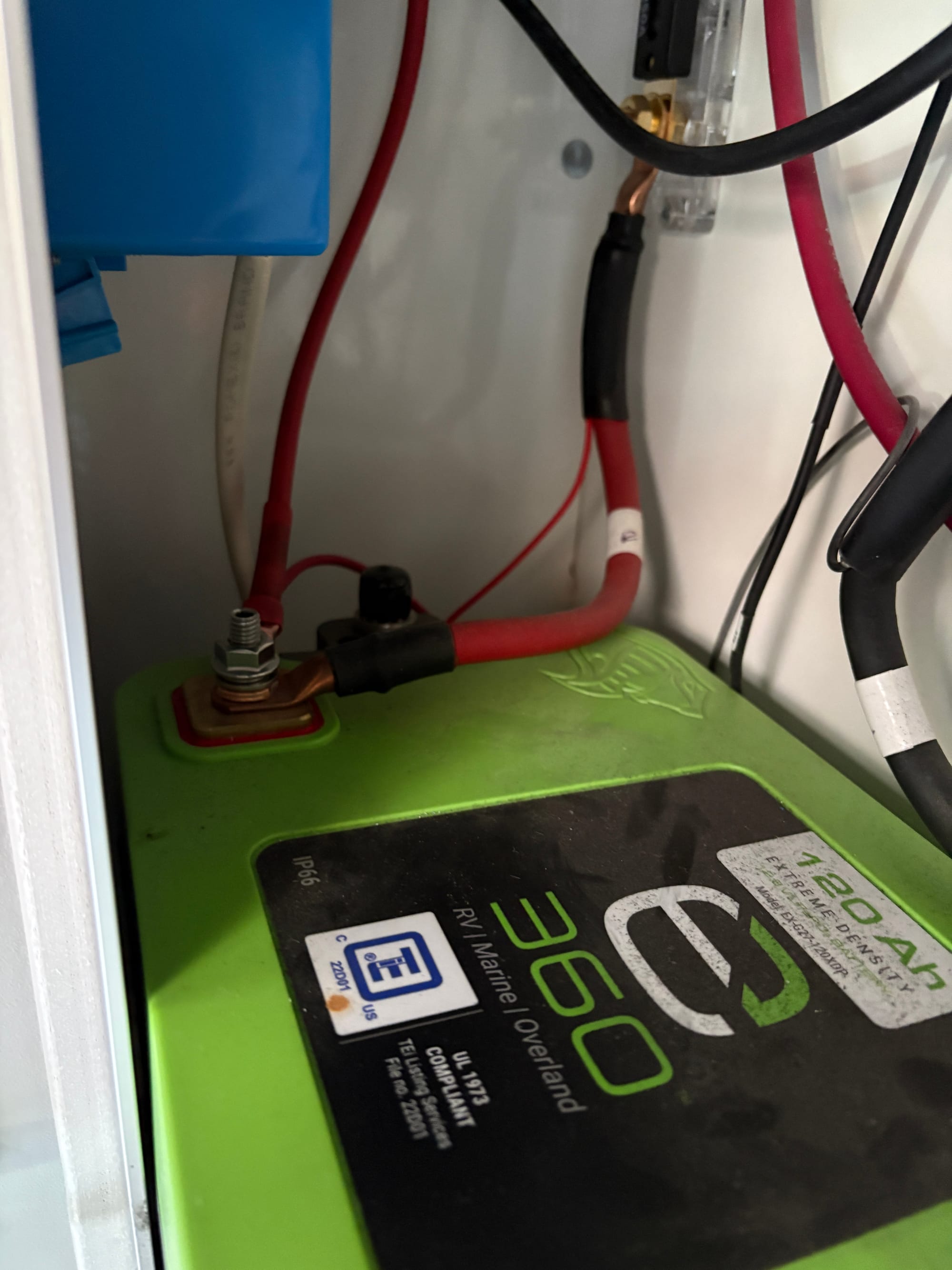
The negative terminal is more complicated. It needs to be connected in the same place as the Zamp. This is on the top nut of the Simarine current sensor shown in figure 1. This allows the Simarine to see the charge current and give an accurate view of the charge state. Do not connect to the battery negative terminal. The battery will charge but the Simarine display will be useless.
This terminal is larger and requires a 7/16” ring terminal. Again use at least 12 gauge wire and crimp the ring terminal to the wire. Remove the nut and washers and add this ring terminal to the stud, replace the washers and nut and tighten it snuggly.
The other end of the wire is cut to length and stripped again 1/2“ and screwed into the negative terminal on the MPPT.
Reconnect the battery negative terminal with care and tighten.
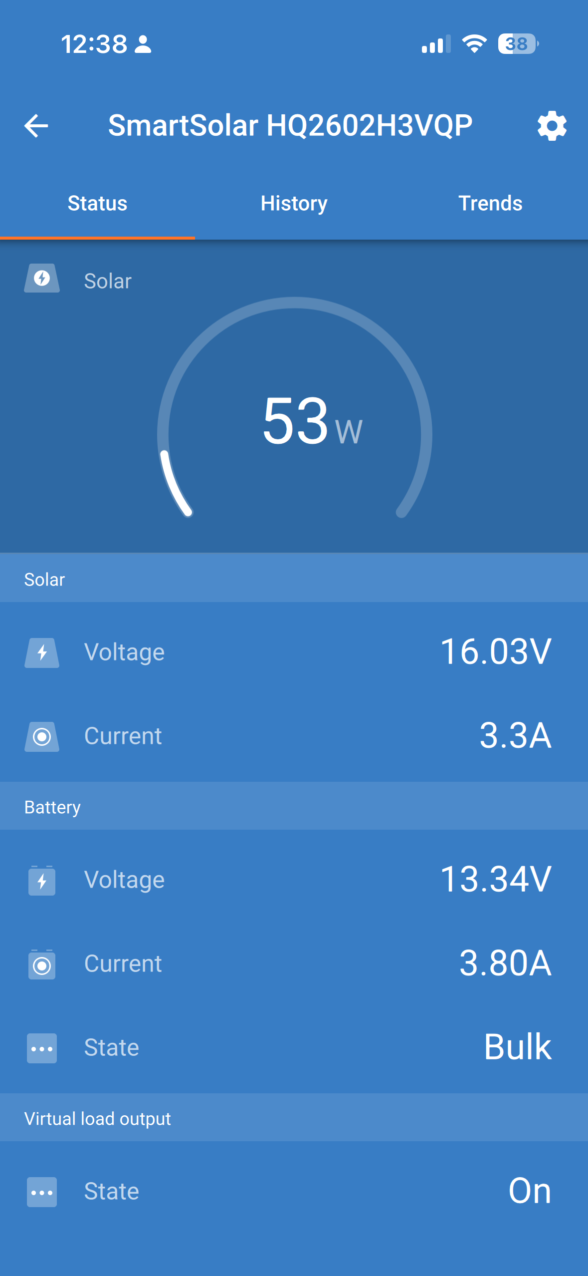
Once the battery is connected to the Victron MPPT then the blue 'Bulk' light blinks and the you can use the app to monitor the state of the charger. Download the app and follow the Bluetooth pairing instructions. The pairing pin is printed on a white label on the side of the Victron and also on an separate label in the box with the unit.
Now connect the solar panel and you should see some voltage on the app status display. You will want to go into settings to ensure the battery-type is set properly as LiFePO.
Mounting
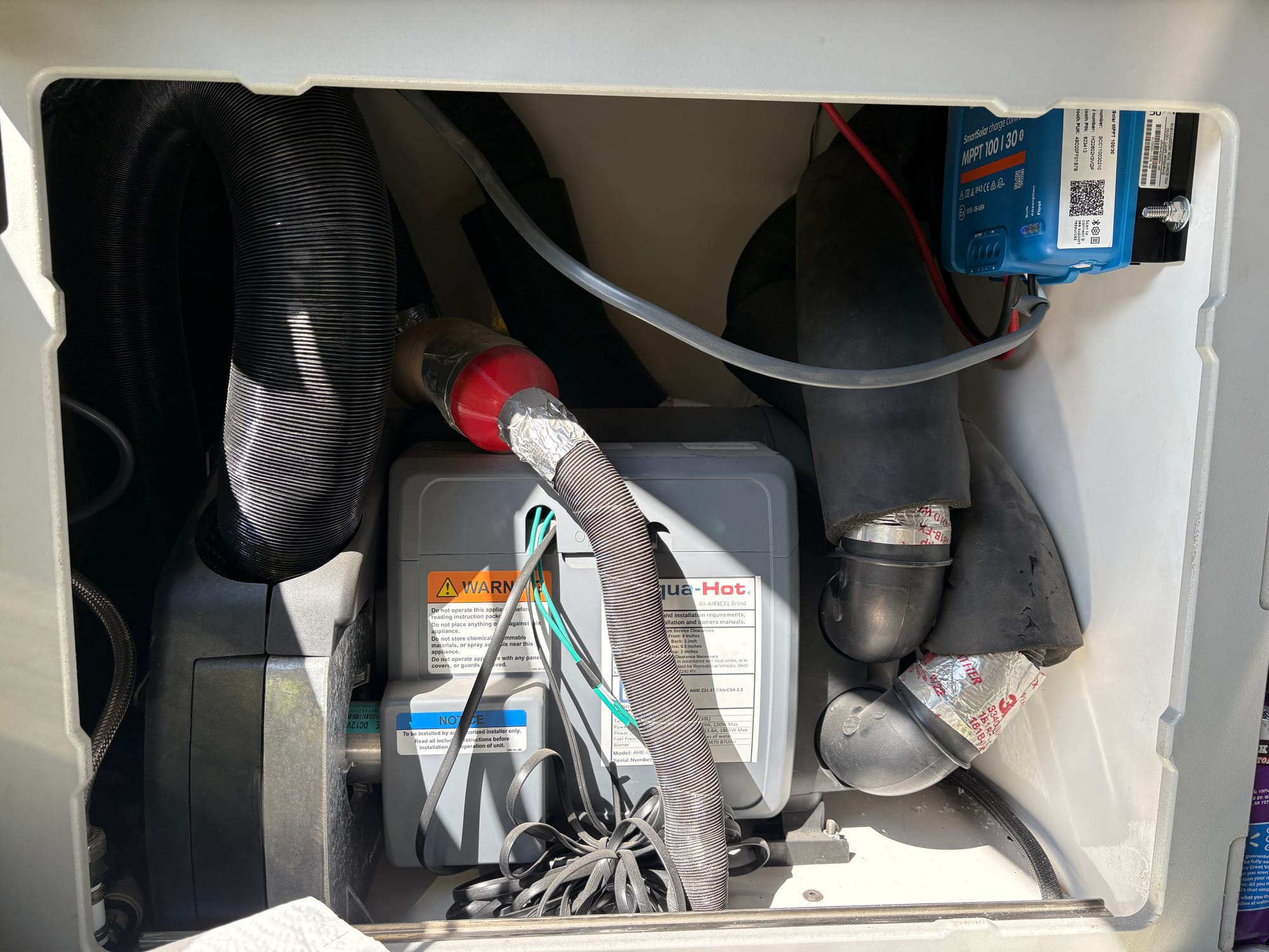
There are a few different mounting options that I considered. If you do not have a second battery or inverter and don’t plan to add them then later there is plenty of space in the battery compartment. I didn’t choose this as it wasn’t clear how to access the other side (though it may be through the cabinets in the bedroom). Escapod chose to use screw inserts in the back panel so this could be an option.
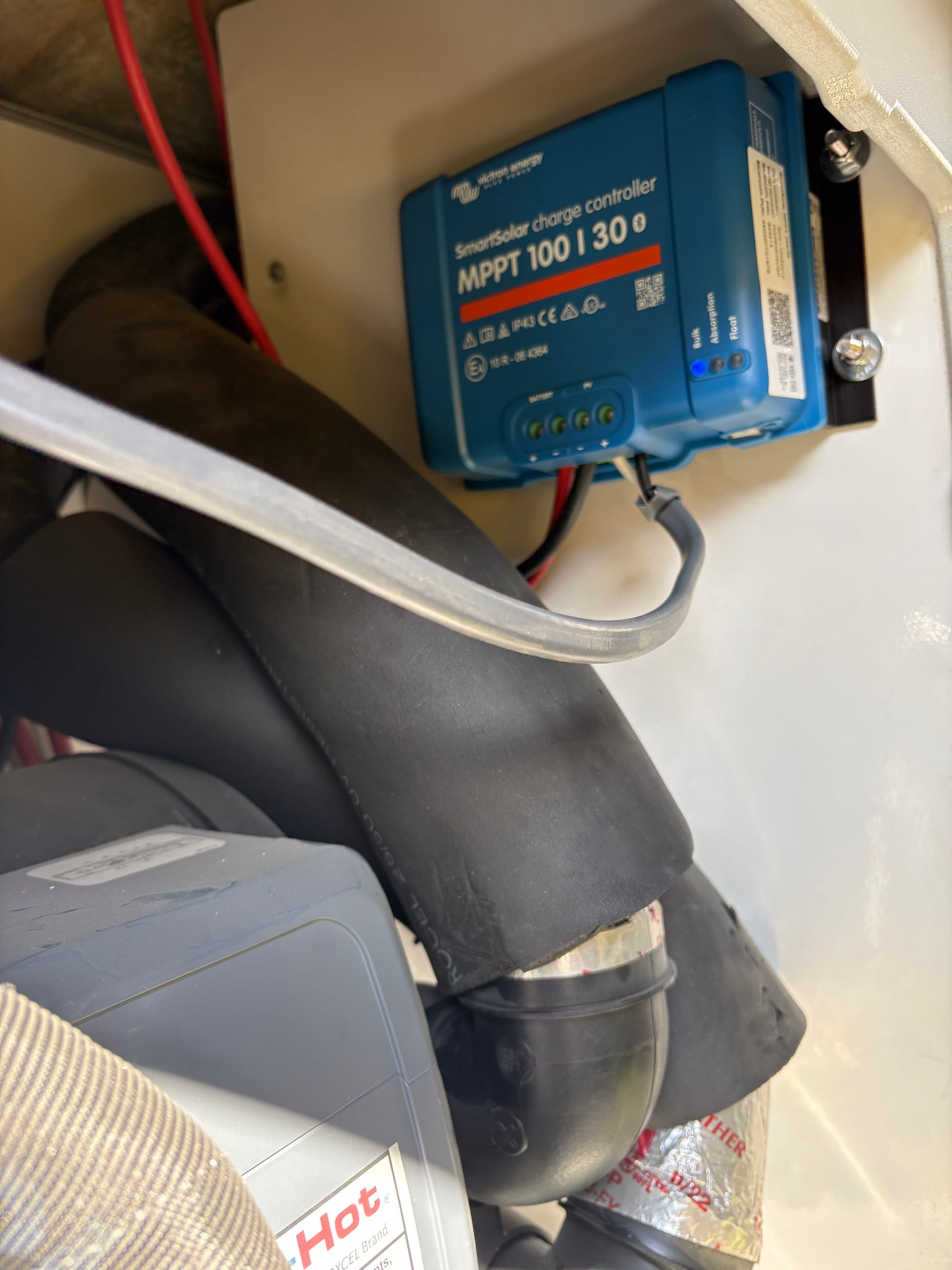
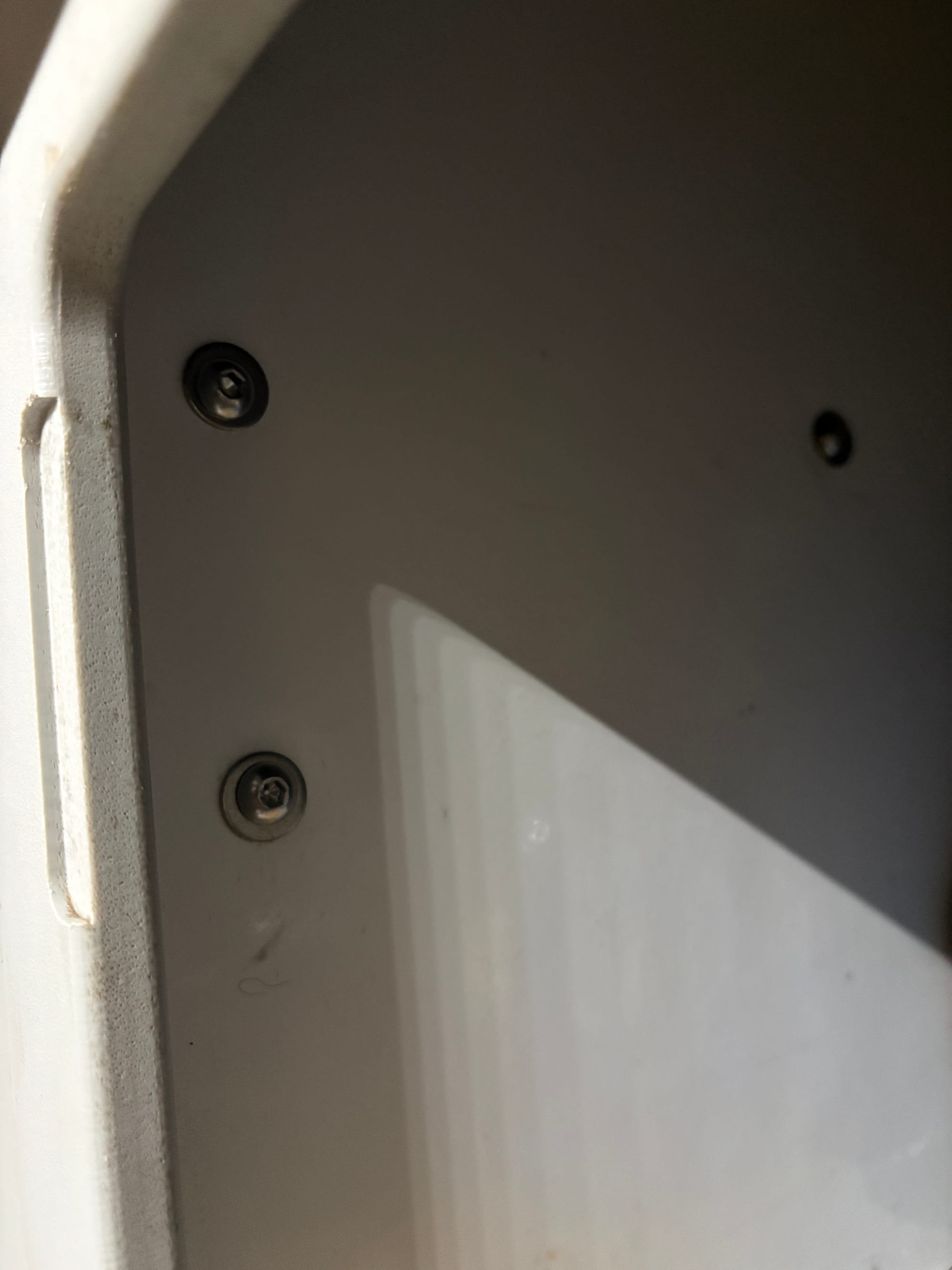
Ultimately I chose to mount the unit on the right sidewall inside the Truma cabinet. I could access the other side from the nearest cabinet to tighten the bolts. Because of the Truma ducts, I could only manage drilling three of the four mounting holes but that should be fine. Victron recommends mounting with four inches of clearance below and above the unit for convection airflow.
I chose 1/4-20 stainless panhead hex bolts with stainless nylon locking nuts along with washers. The nylon locking nuts are essential given the rough travel my Escapod endures.
Results
The results are very satisfying. There is a big improvement in the amount of power available from the panel.
The first tests showed a peak of 101 watts on a day with some smoke and overcast. I am hoping to see some better results when the skies improve. This is a 50% improvement in charging power.
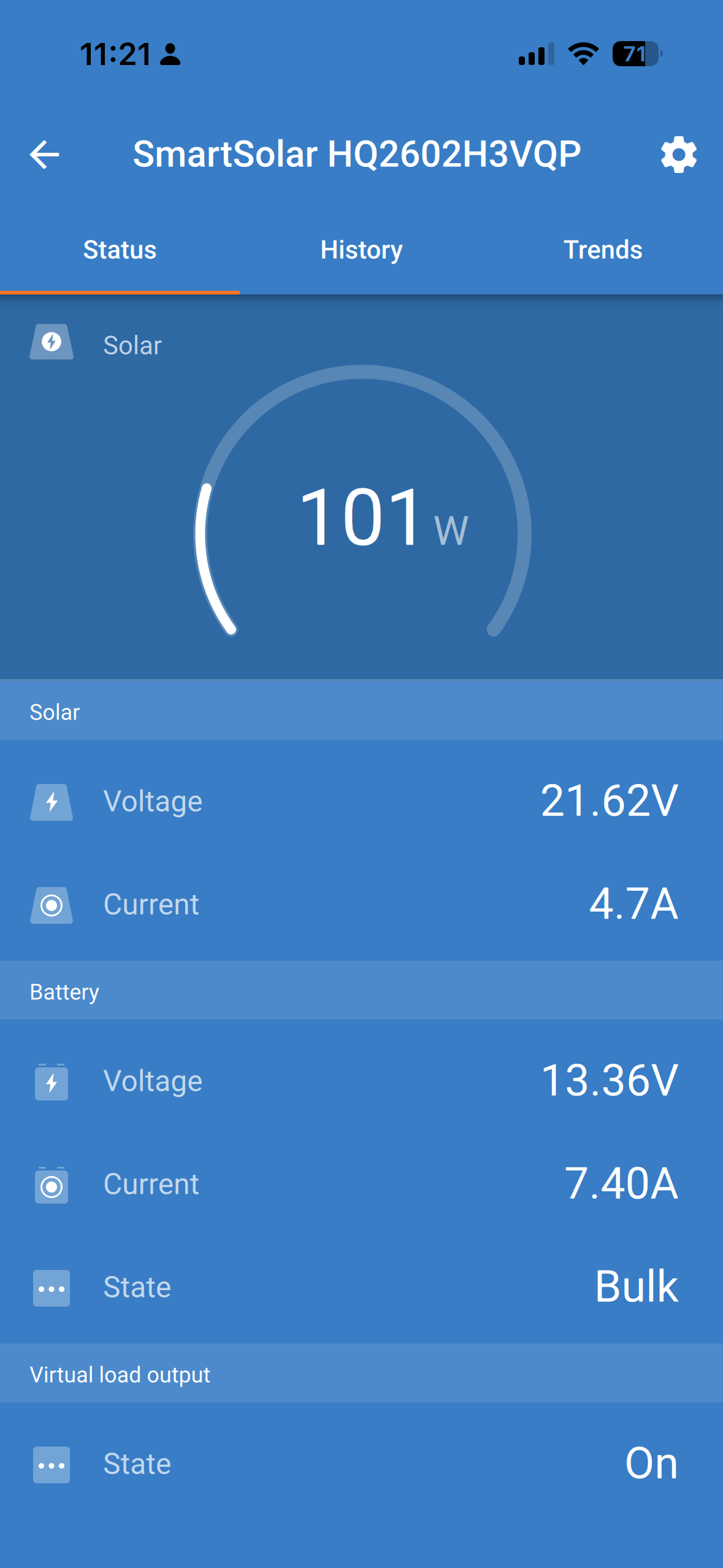
For a comparison you may take the battery charge voltage above and multiply it by the solar current as a good proxy for what a PWM charger controller would give. In the example above this would result in 13.36 volts x 4.7 amps = 62.8 watts so the MPPT delivers 62% more power than the old Zamp.
As a further example of improvement we finally got a clear day with no smoke and strong sunlight. I ask Chat GTP what was the optimum power I could expect at my location and when the peak sun time would be with the panel facing the sun at that time. It stated...
Your panel will be close to the day’s best sun angle—solar noon is around 12:50 p.m. If the panel is tilted toward the Sun, expect approximately:
Clear day: about 80–95% of its rated output
For a 140 W panel: roughly 110–133 W
Under ideal, cool conditions: it might briefly approach 140 W
The rating is based on laboratory conditions: 1,000 W/m² of sunlight and a cell temperature of 25°C. Real panels usually produce less because of heat, wiring losses, the charge controller, and atmospheric conditions.
I was able to hit 130 watts, the best I would see on the Zamp would be 65 watts as I said above and if I take the solar current multiplied by the battery voltage at the time I only get about 80 watts. Again at least 62% improvement and double what I was able to observe in the past.
All of this without the trouble of adding solar panels. The benefits will accrue across additional panels as well as the ability to utilize higher power that would come with the addition of more panels
Extensions and Shading
I have made a couple of wiring adapters to add a second PV panel. One is wired in series which is generally preferred for maximum efficiency and the other is wired in parallel which should give better results with shading.
Shading has a big impact on panel power output. A quick test is shown below. The panel is left in full sun and a screenshot is taken of the charging power. Then I raise may arm to cast a small shadow and another screenshot is taken. The decrease is substantial.
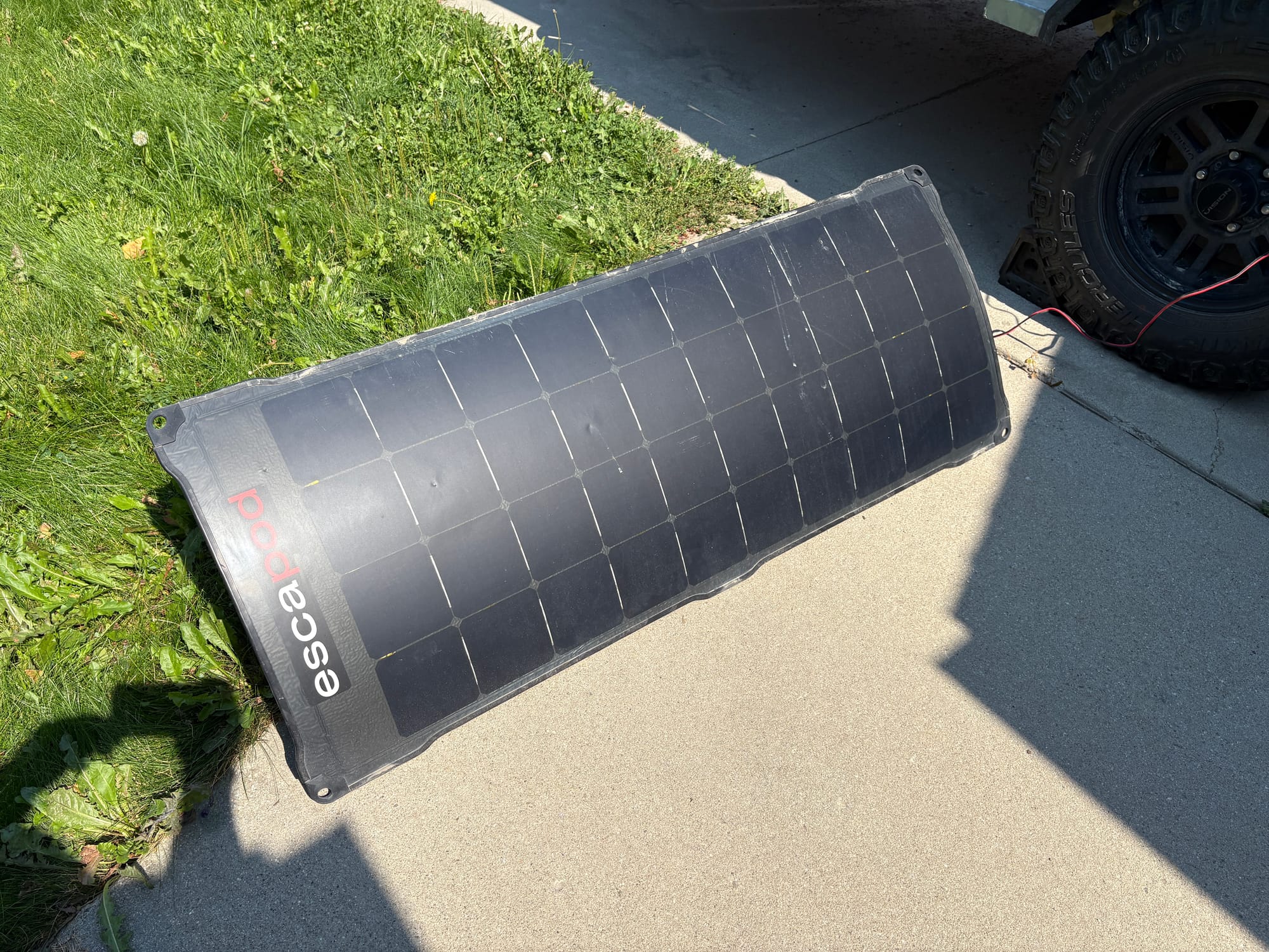
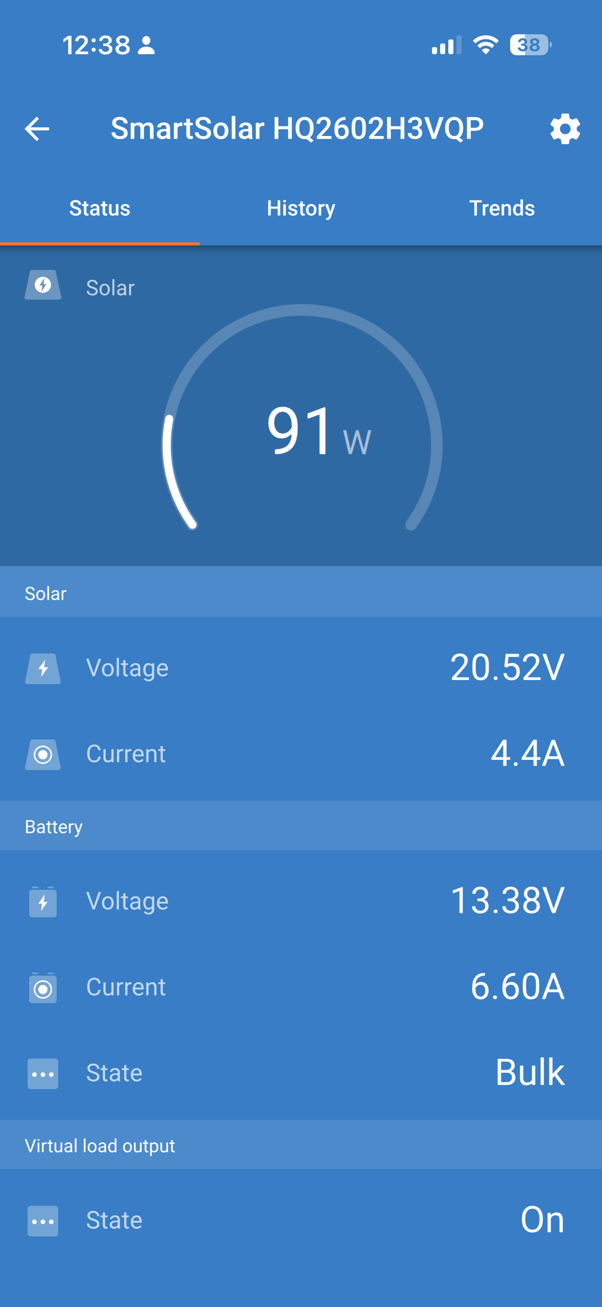
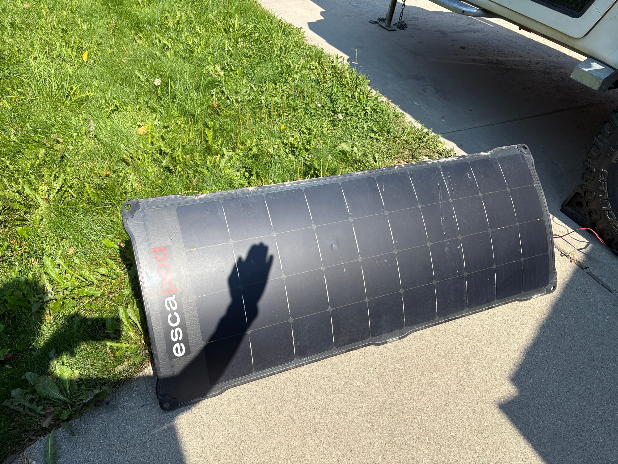
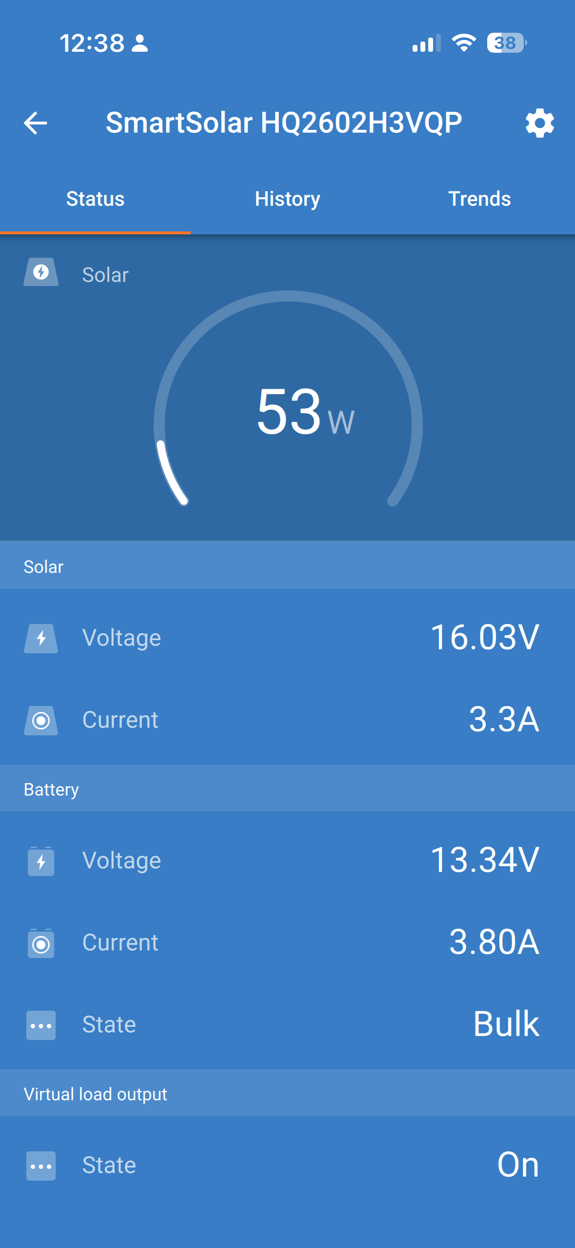
Impact of shading on charging power.
Connecting another panel in parallel will increase the overall charging rate and also help mitigate shadows if one panel is in shadow and the other is not.
Parallel wiring requires, however, that the panels have closely matched voltages. The Escapod panel is a 25v panel so I bought a 25v 100 watt flexible panel to match.
I first wired them (140W + 100W) in parallel and got 175W (20.47 @ 8.5A). (This day had some thin high cirrus clouds)
Next I wired them in series and got 173W (47.75v @ 3.6A) In parallel the currents add and in parallel the voltages add but the power is basically the same.
Because it is easier to add panels in series I tried adding a third 100W panel just for grins and got 255W (71.73v @ 3.6A).
Next I tested the shadow tolerance by shading the right two columns of cells on the Escapod panel. For parallel connection this resulted in 90W (22.6v @ 4.0A) and for series connection 84W (24.02v @ 3.5A).
There is a slight nod towards parallel wiring which in general is what is recommended for shadow mitigation. Clearly shadows are to be avoided as they are a great detriment to power generation. However I wouldn't want to be chasing the sun as my only camping activity.
Series wiring as stated above makes it easier to add more panels as they connect to each other directly whereas parallel means wiring additional connectors. There are parallel panel wiring adapters that help with this though.
Series wiring because it raises voltage, means it is more efficient for longer cable runs. A longer cable increases the resistance and the power loss is a function of the square of the current times the resistance. (P= I^2R) which is why the power grid sends power long distances at very high voltages. Generally for around the campground it probably makes no perceptible difference.